Bioelectricity: Core principles
 Capacitor
Capacitor Any conductive material can be considered as an electrical component for storage of electrical charge or as a source of electrical charge. We concentrate here on the first function. The amount of charge stored per applied voltage is called the capacitance and is measured in units of farads (with symbol F, from Faraday). A capacitor is an electrical component with a large capacity.
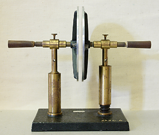
A capacitor is in traditional equipment composed of two flat conductive plates with a relatively large surface area, which are located close to each other and are separated by nonconductive material, or a vacuum, the so-called dielectric. Below is a photo of classical planar capacitor with air and glass as dielectric, which was used for educational purposes (Source: Schul Historic Sammlung Bremerhaven)

When one conductor is positively charged with respect to the other, the electrons bound to molecules in the dielectric move a little bit to the positively charged conductor. The name 'conductor' is derived from the Latin verb condensare, which means compressing, and in the context of a plate capacitor relates to the charges that can be compressed at the flat plates of the capacitor.
Symbol for a capacitor The symbol for a capacitor in an electrical circuit represents the construction of a planar capacitor, and has two variants, namely
![]()
The right-hand symbol is used for a polarised capacitor, better known as "electrolytic capacitor" (abbreviated: elco), which has a positive and negative side; the curved line segment is used as an indication that there is negative charge accumulated on that side, while the other conductive side is positively charged. In the left-hand symbol for a bipolar capacitor we do not distinguish between positive or negatively charged charge. This symbol resembles that of a voltage source, but the vertical lines have the same length and thickness for a capacitor.
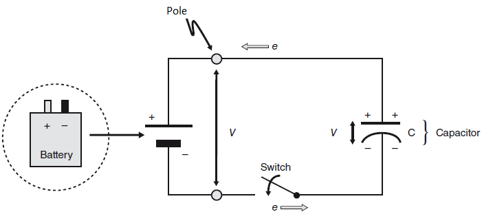
Charging of a capacitor Imagine that you connect the poles of a battery, which supplies a source voltage \(V\), via a conductive wire, and a switch with a planar capacitor; see below the drawing of the electric circuit.
 When you close the switch and create a closed electrical circuit, the potential difference between the poles of the battery forms an electric field in the wire so that electrons start to flow: the electrons from the upper plate of the planar capacitor flow to the positive terminal of the battery and thus positive charge is left on the plate. The electric field at the same time causes an equally large number of electrons to move from the negative pole of the battery to the lower plate of the capacitor and provide there a negative charge. The charging of the capacitor continues until an equally large but opposite charge is present on both plates, and the potential difference between the plates corresponds to the voltage supplied from the battery. We have at that time for the charge \(Q\) on the upper capacitor plate the formula \[Q=C\cdot V\] We will later discuss in detail the process of charging a capacitor. However, what is striking is that the capacitor eventually passes little current (only leakage current).
Formula for capacitance We conclude with notifying that the capacitance \(C\) of a flat plate capacitor is directly proportional to the surface area \(A\) of the plates, and the dielectric constant \(\epsilon\) of the intermediate material, and is inversely proportional to the spacing \(d\) between the plates via the following formula \[C=\frac{\epsilon\cdot A}{d}\]


