Bioelectricity: Core principles
 Capacitors connected in series and in parallel
Suppose you have two capacitors with capacitance \(C_1\) and \(C_2\) connected in an electric circuit in series or in parallel, then you can replace them with a single capacitor with equivalent capacitance \(C_\mathrm{eq}\) given by one of the following relationships.
Equivalent capacitance with a connection in series \[\frac{1}{C_\mathrm{eq}}=\frac{1}{C_1}+\frac{1}{C_2}\qquad\text{connection in series}\]
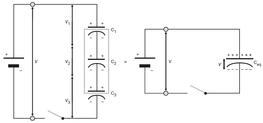
The charging of capacitors that are connected in series is slightly different from the charging of a single capacitor. In the circuit below, we connect three capacitors in series with each other and we derive the formula for the replacement by a single equivalent capacitance in this situation.

When the switch is closed electrons move from the upper plate of the first capacitor having a capacitance \(C_1\) to the plus pole of the battery leaving a positive charge on the upper plate of the first capacitor, and at the same time from the minus pole of the battery to the lower plate of the third capacitor having a capacitance \(C_3\). There is no direct connection between the second capacitor \(C_2\) and the battery. The flow of charge between the plates of the second capacitor must therefore be induced by the charges on the upper plate of the first capacitor and the bottom plate of the third capacitor. The negative charge on the lower plate of the third capacitor repels electrons on the top plate of the third capacitor and makes them flow to the lower plate of the second capacitor. They leave a positive charge on the upper plate of the third capacitor and lead to a negative charge on the lower plate of the second capacitor. Similarly, electrons of the top plate of the second capacitor are repelled by the negative charge on the lower plate of the second capacitor, and this leads to a negative charge on the lower plate of the first capacitor and to a positive charge on the top plate of the second capacitor. Once the voltage across the three capacitors together equals the source voltage \(V\) which the battery supplies, then the flow of electrons stops and we have fully charged capacitors.
Because the charge on the capacitor plates is induced they must be equal to each other anywhere, say the size \(Q\). Thus: \[Q=Q_1=Q_2=Q_3\] If the charge remains the same, but the capacitor area over which the charge is distributed is increased, the voltage will decrease over the whole circuit component. In a series connection of capacitors, each capacitor represents an additional surface area for the same charge to be redistributed. As a result, there is a drop in potential per capacitor from top to bottom in the circuit. The sum of the voltage across the three capacitors is equal to the source voltage supplied by the battery. In formula form: \[V=V_1+V_2+V_3\] The general relationship between charge \(Q\) and voltage \(V\) for a capacitor having a capacitance \(C\) is \(Q=C\cdot V\) and this gives with the substitution of the following equation: \[\frac{Q}{C}=\frac{Q_1}{C_1}+\frac{Q_2}{C_2}+\frac{Q_3}{C_3}\] Because \(Q=Q_1=Q_2=Q_3\), division by \(Q\) leads to: \[\frac{1}{C}=\frac{1}{C_1}+\frac{1}{C_2}+\frac{1}{C_3}\] The three capacitors in series can thus be replaced by a single capacitor having a capacitance \(C\) or \(C_{\mathrm{eq}}\) given by \[\frac{1}{C_{\mathrm{eq}}}=\frac{1}{C_1}+\frac{1}{C_2}+\frac{1}{C_3}\] In the above figure, the equivalent capacitor, also known as a replacement capacitor, is visualized with a larger surface area for the storage of charge (a wider line segment).
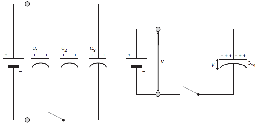
We derive the formula for the equivalent capacitance of three capacitors connected in parallel.
Capacitors that are connected in parallel and are connected to the battery poles via a conductive wire, as shown in the diagram below, together store the charge \(Q\) to that supplied by the battery. Therefore: \[Q=Q_1+Q_2+Q_3\] The potential difference across each capacitor is equal to the source voltage supplied by the battery: \[V=V_1=V_2=V_3\] The general relationship between charge \(Q\) and voltage \(V\) for a capacitor having a capacitance \(C\) now gives by substitution \[CV=C_1V_1+C_2V_2+C_3V_3\] and by division with \(V=V_1=V_2=V_3\) we get \[C_{\mathrm{eq}}=C_1+C_2+C_3\] The replacement capacitor for the three capacitors has a capacitance equal to the sum of the capacitances of the three components.


