Bioelectricity: Core principles
 Resistors connected in series and in parallel
Suppose you have two resistors \(R_1\) and \(R_2\) connected in an electric circuit in series or in parallel, then you can replace them with a single resistor with equivalent resistance\(R_\mathrm{eq}\) given by one of the following relationships.
Equivalent resistance with a connection in series \[ R_\mathrm{eq}=R_1+R_2\qquad\text{connection in series}\]
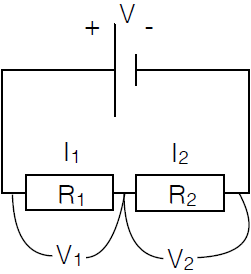
When two resistors in an electrical circuit to be connected in series, as shown in the diagram, then there is a potential gradient within each component given by Ohm's law \(V_R=I\cdot R\). The sum of the two different voltage equals the source voltage \(V\) supplied by the battery. In formula form \[V=V_1+V_2\] No charge can accumulate at one location in the circuit and thus the current across the circuit equals \[I=I_1=I_2\] These two equations together lead to: \[IR = V = V_1+V_2= I_1R_1+I_2R_2 = IR_1+IR_2=I(R_1+R_2)\] So: \[R=R_1+R_2\] The resistors connected in series can thus be replaced by a single resistor with a resistance \(R_{\mathrm{eq}}\) that is equal to the sum of the resistances of the resistors connected in series.

Equivalent resistance with a connection in parallel \[\frac{1}{R_\mathrm{eq}}=\frac{1}{R_1}+\frac{1}{R_2}\qquad\text{connection in parallel}\]
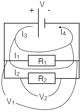
Two resistors that are connected in parallel and are connected to the battery poles via a conductive wire, as shown in the diagram below, have the same potential difference as supplied by the battery. Therefore: \[V=V_1=V_2\] The current \(I_3\) splits into two branches, namely \(I_1\) and \(I_2\), which come later back into a single current \(I_4\). Because no accumulation of charge can arise we have: \[I_3=I_4=I_1+I_2\] Let \(I_3=I_4\) be simply refered to as \(I\) and the equivalent resistance be denoted by \(R_{\mathrm{eq}}\). Then we can apply Ohm's law to the equation \(I=I_1+I_2\) and rewrite it as \[\frac{V}{R_{\mathrm{eq}}}=\frac{V_1}{R_1}+\frac{V_2}{R_2}=\frac{V}{R_1}+\frac{V}{R_2}=V\left(\frac{1}{R_1}+\frac{1}{R_2}\right)\] Division by \(V\) leads to \[\frac{1}{R_{\mathrm{eq}}}=\frac{1}{R_1}+\frac{1}{R_2}\]

In which way could you then construct an electrical circuit with an equivalent resistance equal to \(32\,\Omega\) with thr smallest possible number of resistors available?
In series connections, the equivalant resistance is equal to the sum of the resistances involved.
In series connections, the reciprocal value of the equivalant resistance is equal to the sum of the reciprocal values of the resistances involved.
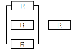
The component in an electrical circuit with the smallest possible number of resistors of \(24\,\Omega\) that has an equivalent resistance equal to \(32\,\Omega\) consists of 3 parallel resistors which are hereafter connected in series to a single resistor, as shown in the diagram with \(R=24\,\Omega\):


