Bioelectricity: Core principles
 Electric circuits
We have already seen electric circuits with a voltage source and capacitors that are only connected in series or parallel or resistors that are only connected in series or parallel. But combinations of such electrical components are also permitted. Via the so-called Kirchhoff's rules we can compute voltages and currents in parts of such general electric circuit.
Kirchhoff's junction rule From the principle of conservation of electric charge follows:
At each node in an electric circuit, the total sum of the currents flowing in that section is equal to the total sum of the currents that depart from that point. The node cannot store or release current.
In other words, at each node is the algebraic sum of the currents (in which current inflows are taken positive, and current outflows are taken negative) equal to zero: \[\Bigl(\sum_{\begin{aligned} &k\mathrm{\,th\;current}\\ &\mathrm{via\;node}\end{aligned}}I_k \Bigr)= 0\]
Say you have a node \(N\) in a circuit as shown in the figure below.
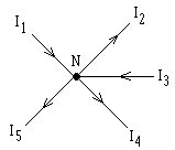
Then: \[I_1-I_2+I_3-I_4-I_5=0\]
Kirchhoff's loop rule From the principle of conservation of energy follwos:
The sum of the electric potential differences in each closed loop in a circuit is equal to zero.
Here we must take into account the direction: the default option is to count the voltage drop as positive in the direction of the current and negative if we are going across a component in the direction opposite to the current. In addition, the voltage difference across a voltage source is the opposite of the supplied voltage.
In other words, in each complete loop is the algebraic sum of the voltages (taking into account the direction) equal to zero: \[\Bigl(\sum_{\begin{aligned} &k\mathrm{\,th\;voltage\;in}\\ &\mathrm{loop\;of\;circuit}\end{aligned}}V_k \Bigr)= 0\]
Suppose that you have an electric circuit as shown in the figure below, consisting of two resistors connected in parallel, which are in turn connected in series with a third resistor.
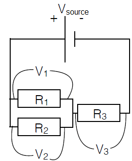
When we consider the loop consisting of the voltage source and the resistors \(R_1\) and \(R_3\), then Kirchhoff's loop rule gives \[V_1+V_3-V_\mathrm{source}=0\] When we consider the loop consisting of the voltage source and the resistors \(R_2\) and \(R_3\), then Kirchhoff's loop rule gives \[V_2+V_3-V_\mathrm{source}=0\] It also follows that \(V_1=V_2\).
Worked-out example of an electric circuit Let's work out the previous example a bit more. We extend the picture with symbols for electric currents.
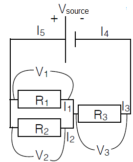
Kirchhoff's junction rule gives the following equations \[\begin{aligned} I_5-I_1-I_2&=0\\ I_1+I_2-I_3&=0\\ I_3- I_4&=0\\ I_4-I_5&=0\end{aligned}\] This can be rewritten as \[I_3=I_4=I_5, \qquad I_1+I_2=I_3\]
Kirchhoff's loop rule gives, as we have seen before, two equations \[V_1+V_3-V_\mathrm{source}=0, \qquad V_2+V_3-V_\mathrm{source}=0\] This can be rewritten as \[V_1=V_2, \qquad V_2+V_3 = V_\mathrm{source}\]
In addition, Ohm's law holds for any resistance. This gives three more equations: \[V_1=I_1R_1,\qquad V_2=I_2R_2,\qquad V_3=I_3R_3\]
In total we get a system of equations. We now consider the source voltage \(V_\mathrm{rource}\) and the resistors \(R_1\), \(R_2\) and \(R_3\) as parameters in which the currents \(I_1\), \(I_2,\) and \(I_3\) and the voltage \(V_1\), \(V_2\) and \(V_3\) can be expressed using algebraic formulas. As a concrete example we determine the formula for \(I_3\).
From \[V_1=I_1R_1,\qquad V_2=I_2R_2,\qquad V_1=V_2\] follows \[I_1R_1=I_2R_2\] Because \[I_1=I_3-I_2\] we have \[(I_3-I_2)R_1=I_2R_2\] This can be written as \[I_3R_1=I_2(R_1+R_2)\] Thus: \[I_2=\frac{I_3R_1}{R_1+R_2}\] Substituting this equation into the equation \[V_\mathrm{source}=V_2+V_3=I_2R_2+I_3R_3\] gives \[V_\mathrm{source}=\frac{I_3R_1R_2}{R_1+R_2}+I_3R_3=I_3\left(R_3+ \frac{R_1R_2}{R_1+R_2}\right)=I_3\left(R_3+\frac{1}{\displaystyle \frac{1}{R_1} +\frac{1}{R_2}}\right) \] So: \[V_\mathrm{source}=I_3R_{\mathrm{eq}}\] where the equivalent resistance \(R_{\mathrm{eq}}\) satisfies \[R_\mathrm{eq}=R_3+\frac{1}{\displaystyle \frac{1}{R_1}+ \frac{1}{R_2}}\] In summary: \[I_3=\frac{V_\mathrm{source}}{R_{\mathrm{eq}}}\] with the previously given formula for the replacement resistance.
Note that for this particular circuit, the formula for the replacement resistance could have be determined much more rapidly by first replacing the parallel resistors \(R_1\) and \(R_2\) by a resistor with resistance \(R_{12}\) defined by the equation \[\frac{1}{R_{12}}=\frac{1}{R_{1}}+\frac{1}{R_{2}}\] i.e. \[R_{12}=\frac{1}{\displaystyle \frac{1}{R_1}+ \frac{1}{R_2}}\] Next you take the equivalent replacement resistance of resistors \(R_{3}\) and \(R_{12}\) connected in series, with the formula \[R_\mathrm{eq}= R_{3}+R_{12}= R_3+\frac{1}{\displaystyle \frac{1}{R_1}+ \frac{1}{R_2}}\]
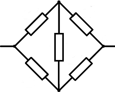
In general, you cannot always rely on the replacement rules for components connected in series or in parallel. For example, this does not work for the following circuit. However, Kirchhoff's rules will function properly in this case.