Bioelectricity: Core principles
 Discharging a capacitor in an RC circuit
Discharging an RC circuit
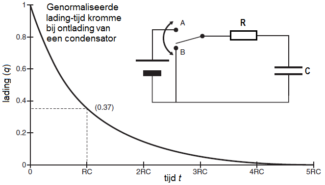
We consider an electrical circuit in which a capacitor having a capacitance \(C\) discharges through a resistor with resistance \(R\) as shown in the electrical diagram in the figure below. First, the switch was set to position A so that the capacitor could be completely \charged. Next, the switch in the RC circuit is placed in position B at time \(t=0\), the battery does not play a role anymore, and the discharge of the capacitor can begin, with the capacitor functioning as a continuously decreasing voltage source

Derivation of a matching differential equation
The above normalized charge-time and current-time graphs can be mathematically described in precise terms. During the discharging process in the RC circuit Kirchhoff's rules apply. The loop rule for voltage states in this case that the voltage drop across the resistor and across the capacitor is equal to zero. In formula form: \[V_R+V_C=IR+\frac{Q}{C}=0\] where \(Q(t)\) is the charge of the upper plate of the capacitor at time \(t\) and \(I(t)\) the current in the closed circuit at time \(t\). The current\(I\) is equal to the amount of charge flowing through the circuit per second at any time and is given, by definition, by the following equation: \[I(t) = Q'(t)\] We therefore have the following differential equation: \[R\frac{\dd Q}{\dd t} + \frac{Q}{C} =0\] or: \[\frac{\dd Q}{\dd t} =-\frac{1}{RC}Q\] This is the differential equation of an exponential decay, which can be written as \[\frac{\dd Q}{\dd t} = -\frac{Q}{\tau}\] with characteristic time \(\tau=RC\), also called RC time.
The differential equation for discharging a capacitor in an RC circuit
An RC circuit is an electric circuit that includes a resistor and capacitor in series, with resistance \(R\) and capacitance \(C\), respectively, and optionally in series abattery delivering a voltage \(\mathcal{E}\). Assuming no battery, the differential equation of charge for a discharging capacitor in an RC circuit is equal to \[\frac{\dd Q}{\dd t} = -\frac{1}{\tau}\cdot Q\] with characteristic time \(\tau=RC\) and maximum charge \(Q_{0}\) at time \(t=0\). This is a differential equation of exponential decay and the solution of this differential equation is \[Q(t) = Q_{0}\cdot e^{{}^{-\frac{t}{\tau}}}\]
Formulas for normalized charge and current
The normalized charge \(q(t)=\frac{Q(t)}{Q_0}\) is given by \[q(t)=e^{{}^{-\frac{t}{\tau}}}\] At time \(t=\tau=RC\) we have \(q(\tau) = \exp(-1)\approx 0.37\).
\(\phantom{x}\)
We get the formula for the current by taking the derivative of \(Q(t)\): \[I(t)=\frac{\dd Q}{\dd t}=\frac{\dd}{\dd t}\left(Q_0e^{{}^{-\frac{t}{\tau}}}\right)=\frac{Q_0}{\tau}e^{{}^{-\frac{t}{\tau}}}\] The normalized current \(i(t)=\frac{\tau}{Q_0}I(t)\) is given by \[i(t)=e^{{}^{-\frac{t}{\tau}}}\] At time \(t=\tau\) we have \(i(t) = \exp(-1)\approx 0.37\).
The time graphs of normalized charge and current are therefore the same exponential decay curve. Because the charge on a capacitor plate is proportional to the voltage acrrosss the capacitor, this is also true for the normalized voltage across the capacitor.


