Unlimited growth: Applications of exponential growth models
 Discharge of a capacitor
Capacitor Each conductor can be considered as an electrical component for the storage of electrical charge or as a source of electrical charge. We concentrate here on the first function. The amount of charge stored per voltage is called the capacity and is measured in units of farads (with symbol F, from Faraday). A capacitor, also called condenser, is an electrical component with a large capacity.
A traditional capacitor is composed of two flat parallel conductors with a relatively large surface, which are located close to each other and are separated by a non-conductive material, or a vacuum, the dielectric. Below you can see a photo of a classical parallel plate capacitor with air and glass as dielectric, which was used for educational purposes (Source: Schul Historic Sammlung Bremerhaven)
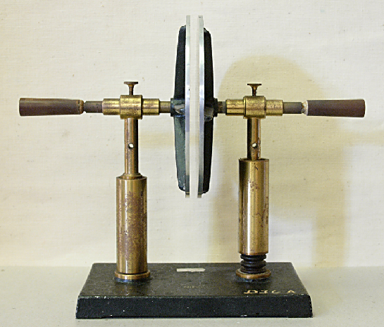
When one conductor is positively charged with respect to the other, electrons bound to the molecules in the dielectric locate themselves a little to the positively charged conductor. The name "condenser" is derived from the Latin verb "condensare", which means compressing. In the context of a plate capacitor this relates to the loads that can be compressed at the flat plates of the capacitor.
Symbol for a capacitor The symbol for a capacitor in an electrical circuit represents the construction of a planar capacitor, and has two variants, namely
![]()
The right symbol, for a polarised capacitor, better known under the denomination "electrolytic capacitor" (abbreviated: e-cap), is used for capacitors that have is a positive and negative terminal. The curved line segment indicates that negative charge accumulates there, whereas the other conductor is positively charged. With the left-hand symbol for a bipolar capacitor, we do not distinguish between positive or negatively charged charge. This symbol resembles that of a voltage source (battery), but with a capacitor, the vertical lines have the same length and thickness.
Charging a capacitor Imagine that you connect the poles of a battery, which give a voltage of \(V\), via a conductive wire and a switch with to a planar capacitor; see the following drawing of the circuit.
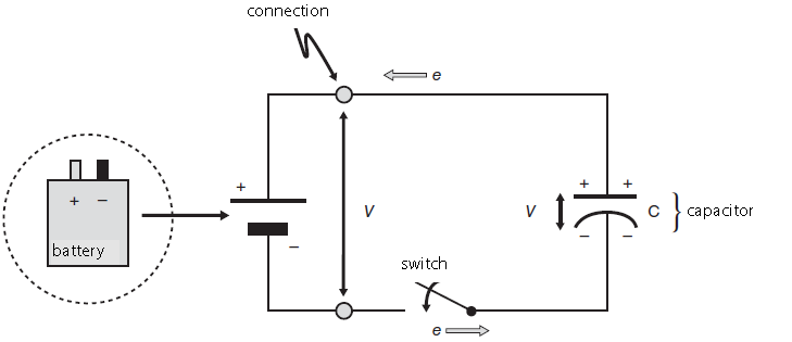 Once you close the switch and create a closed electrical circuit, the potential difference between the terminals of the battery leads to an electric field in the wire, which results in a current of electrons: the electrons will flow from the upper plate of the planar capacitor to the positive terminal of the battery, which results in a positive charge being left on the plate. The electric field at the same time causes an equally large number of electrons from the negative terminal of the battery to go to the lower plate of the capacitor and provide a negative charge there. The charging of the capacitor continues until a charge equal in size but opposite in sign is present on both plates, and the potential difference between the plates corresponds to the voltage supplied from the battery. At that time, there is a charge \(Q\) at the upper capacitor plate, with \[Q=C\cdot V\] We will later look at the process of charging a capacitor in more detail. However, what is striking is that the capacitor eventually passes little current (only a leakage current).
Discharge of an RC circuit We consider an electrical circuit in which a capacitor having a capacitance \(C\) discharges through a resistor \(R\), as shown in the electrical diagram below. First, the switch was set to position A, so that the capacitor could be completely charged. Next, the switch in the RC circuit at time \(t=0\) is placed into position B, so that the battery does not play a role anymore. The discharge of the capacitor now starts, with the capacitor functioning as a continuously decreasing voltage source.
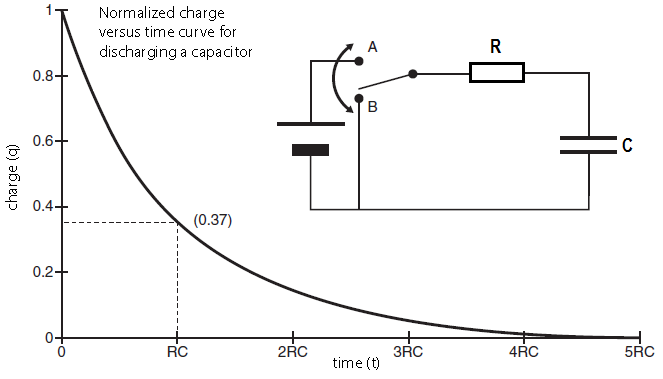
Derivation of a differential equation for a discharging capacitor The normalized charge versus time graph above can be described mathematically. During the discharge process Kirchhoff's laws apply to the RC circuit. The law of voltage states in this case that the sum of the voltage across the resistor and the capacitor is equal to zero. In formula form: \[V_R+V_C=IR+\frac{Q}{C}=0\] where \(Q(t)\) is the charge on the upper plate of the capacitor at time \(t\) and \(I(t)\) the electric current in the circuit at time \(t\). The current \(I\) is equal to the amount of charge that flows through the circuit per second at any time and is given, by definition, by the following equation: \[I(t) = Q'(t)\] We therefore have the following differential equation: \[R\frac{\dd Q}{\dd t} + \frac{Q}{C} =0\] In other words: \[\frac{\dd Q}{\dd t} =-\frac{1}{RC}Q\] This is the differential equation of exponential decay, which can be written as \[\frac{\dd Q}{\dd t} = -\frac{Q}{\tau}\] with characteristic time \(\tau=R\times C\), also called the RC-time. The solution is \(Q(0)=Q_0\) is \[Q(t)=Q_0e^{{}^{-\frac{t}{\tau}}}\]
Electrical analogue of an ion channel in a cell membrane The example above of a capacitor in an electrical circuit might not immediately make you think of biology, biomedical sciences or psychobiology, but it is actually a fundamental property of a neuron: complex electrical properties of a cell membrane can be understood by describing it as an electrical circuit consisting of resistors, capacitors and batteries. Here, the insulating lipid bilayer between the two conductive media of the intra- and extracellular fluid function as the dielectric of a parallel plate capacitor between two conductive plates. This construction is a capacitor with the capacity to store charge when an electric voltage is applied across the dielectric. Each ion channel corresponds to a series-connected battery and resistance, such as visualised in the figure below.
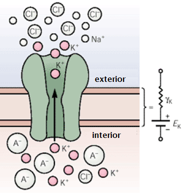
The functioning of the ion channel and cell membrane can then be represented by an electric circuit as shown in the figure below. Herein, \(E_\mathrm{K}\) is the Nernst potential of the ion channel, on the basis of differences in ion concentration inside and outside the cell. The convention in electrophysiology is to select the direction of flow of positive charged particles from the inside to the outside of the cell as a positive current. In a picture (here the \(\mathrm{K}^{+}\) ion; but often the charge is left out and only the name of the ion is depicted) the electric circuit looks like this:
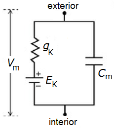
In the above situation, we can deduct from the Kirchhoff's law of currents that at rest \(V_m\) is equal to the Nernst potential \(E_\mathrm{K}\), which is then called the resting membrane potential. In the presence of more ionic channels, the resting membrane potential \(V_r\) will be a weighted average of the Nernst potentials of the ion channels.
Restoration of the resting membrane potential when a stimulus stops If we define \(V=V_m-V_r\), that is, if we look at the potential difference between the current potential and the resting membrane potential, we get the following differential equation for the membrane potential \[I_\mathrm{stim}=C_m\frac{\dd V}{\dd t} + g_\mathrm{\small K} V\] If the stimulus is zero, then the differential equation is the same as that of a discharging capacitor. In a cell which is not at rest, but, for example, has a starting value of the membrane voltage \(V_0\) (non-zero at time \(t=0\)), the voltage will approach the original resting membrane potential via an exponential decay process, according to the formula \[V(t)=V_0\cdot e^{-\frac{ g_\mathrm{\small K}}{C_m}t}\tiny.\]


